Posted on November 11, 2008 in Hydronic Heating by adminComments Off on Phase 1 energy upgrade complete

FOM Systems, Inc. is happy to announce that the first phase of our energy upgrade is complete.  Our wood gassification boiler is up and running, and working like a charm!  We had a late Indian summer this year which lasted until all the pipework and post installation operations were completed, with time to spare.  So far we seem to be using about the same amount of wood daily as we had previously when we were simply firing a wood stove, but now the entire house is warm, not just the downstairs, plus we have a virtually unlimited supply of domestic hot water.  We are still experimenting with the boiler firing rate, and yes, it is possible to put too much wood in at one time, as well as too little it seems.

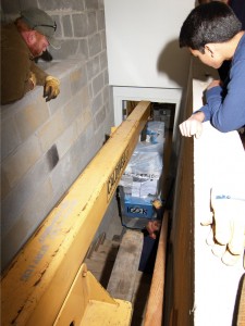
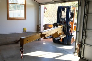
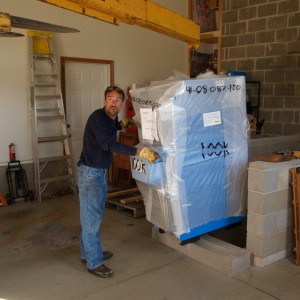
So, how does one move a 1700 pound piece of machinery up one and down 16 steps through a narrow stairway and into the basement?  Very carefully!  Step one is to gather the right equipment.  Russ brought his forklift with an extension beam on it.

Using a forklift with extendable beam

Using a forklift with extendable beam

At the distance we needed the moment arm was calculated to be able to lift about 3100 pounds so we decided this was the best option to use to get the boiler downstairs.

Ready to start the long descent

Ready to start the long descent

Once we were all done measuring things and got the boiler unbolted from its pallet, everything was fairly straightforward, until we got to the bottom of the stairwell…

Can we get it through the door???

Can we get it through the door???

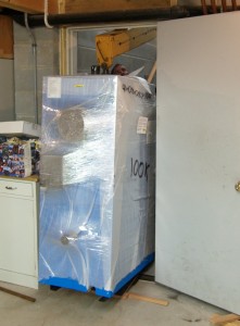
With a bit of head scratching, adjusting the beam, and a change of the clevis securing the lifting ring of the boiler to the beam, we were able to get the boiler through the door and set it flat on the basement floor, with essentially no room to spare up and down. There was plenty of side clearance to get through the door.

Boiler just barely fits through the door, with the beam attached.

Boiler just barely fits through the door, with the beam attached.

Once we were able to get the boiler sitting on the floor inside the door, moving it around inside the basement was simple using a couple of skates and a Johnson bar. But anyway, that was the end of the most exciting part of the whole affair. We still had a lot of plumbing ahead to connect the boiler to the new storage tank and the existing radiant system.

Posted on September 29, 2008 in Hydronic Heating by adminComments Off on Preparing for boiler arrival

The new wood gassification boiler should be here in a week or two.  In the meantime we’ve been preparing the way by getting the old oil storage tank out of the way and installing a 650 gallon water storage tank from STSS, Inc.  I’ve finally gotten my head around the design of the piping system and worked out the needed sizes and flow rates for everything.
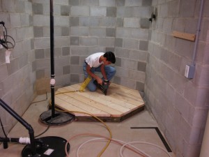
Preparing a platform for the storage tank

A couple of unusual items, at least for a residential hydronic system, will be a 4 way flow control valve which is used to reverse the flow rate through the main heat exchangers in the tank, and a variable speed circulator which will be used to regulate the rate of heat transfer into and out of the tank in order to maximize the boiler operating efficiency.  The latest piping diagram is here.
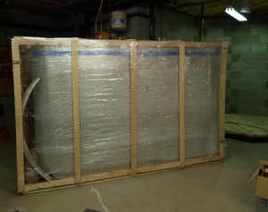
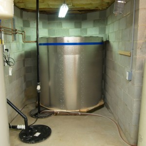
Tank still in its shipping crate
Tank set up in place, no plumbing

So far the tank is sitting in place (empty of course), and the DHW heat exchanger has been connected already.  We had to add a tempering valve to the INPUT of the DHW tank to keep it from overheating and to reduce efficiency losses.  Leaving off the tempering valve might not be a bad idea in some cases though- a friend of mine who has a Hardy outdoor wood boiler and is heating DHW with it without benefit of a tempering valve finds that his daughters are not able to stay in the shower for a long time anymore since the rising water temperature drives them out!

System control strategy

With a rated output of 100,000btu, the EBW-100 boiler is able to deliver more heat than the house can consume (at the 1 degree F. design point, maximum heat input is calculated to be around 84809btu/hr, given the radiant piping plan and the flow rates chosen, with building total heat loss of 46770btu/hr).  We don’t often see that kind of demand around here, though occasionally the temperature will drop below 0°F.  The lower the heating demand on the boiler, the more heat will be available to charge up the tank.  To maximize the efficiency of the boiler, it’s necessary to keep it operating continuously (no interruptions in forced combustion air) until the load of wood is consumed.  Not only that, the water temperature should be kept around 160F, which is high enough to avoid condensation problems with flue gases, but low enough to ensure peak operating efficiency.  Maximum boiler water temperature is 180F, whilst maximum storage tank water temperature is 170F due to its construction.  In order to be able to transfer 100,000btu/hr continuously to the tank without the boiler getting ahead of it, we have to maintain a high volume of flow through the heat exchangers and try to limit the differential temperature from tank input to output to some reasonable amount.  It turns out that a delta-T of about 20F at a flow rate of 10gpm is enough to maintain a transfer rate of 100,000btu/hr.  As the tank temperature approaches 160F the boiler output will have to start backing down, since with the water temperature limit being 180F, the heat transfer rate to the tank will begin to decline as the delta-T will begin dropping below the 20F design setpoint.  The circulator should be operating at maximum flow rate at this time in the cycle.  Ideally, the load of wood should be almost completely burned off by the time the tank reaches 160F so that the boiler output can begin backing down just as the heat transfer rate from boiler to tank begins to decline.  Ideally the boiler and tank would both reach steady state of around 170F at which point the tank circulator would shut off.  The house zones would be used as a heat dump in the event the boiler temperature is still above 170F when the tank reaches this limit.  As a last resort, the combustion air would be turned off, shutting down secondary combustion and damping the fire.

When the house is coming up to temperature and pulling heat out of the boiler, the tank has to be throttled back somehow to avoid overloading the boiler.  As the house heating loops reach steady state, more heat will become available to transfer into the tank.  Since a rather large circulator will be used for the tank loop, it seems inefficient to cycle it on and off to provide this control, since when the tank is cold and the house is taking heat, the ‘on’ cycles will be very short.  Also, since we don’t need to take heat out of the tank nearly as fast as we put it in, it also seems wasteful to cycle the circulator as a means of reducing the rate of heat being drawn from the tank.  It’s desirable to maintain the primary loop temperature no higher than that needed by the highest heating zone, currently about 130F, to minimize the rate of heat transfer needed from the tank.  Taco makes variable speed circulators that will accomplish this control task very elegantly.  A single 0011VV-IFC variable speed circulator with integral flow check should do the job nicely.  Based on the hydraulic resistance curve of the tank loop we should be getting just over 10gpm when the pump is at full speed.

Note also we use a 4 way flow control valve to reverse the direction of fluid flow through the tank heat exchangers so that we always put heat in from the top (coolest water is fed to boiler return) and take heat out from the top (highest temperature water is fed to the primary loop).  So it looks like the computer software is going to need some upgrading to do PID control of the tank circulator.  More temperature sensors need added as well, as we monitor the temperature of the tank at the top, middle, and bottom to gauge the extent of heat stratification in the tank.  With winter just around the corner it seems to make sense to defer installation of the solar collectors until next year, or when funds permit.  Wood is starting to get a little more difficult to come by, seems everyone all of a sudden has decided that oil is no longer viable!
Posted on August 22, 2008 in Hydronic Heating by adminComments Off on Boiler Piping Design

Whilst waiting for the arrival of the new wood fired boiler we need to prepare the storage tank and get the piping scheme worked out for the system. We’ve selected a 659 gallon 64×60 tank from STSS Co., Inc., with 3 heat exchanger coils: one dual coil for heating system input/output, one coil for the solar array, and one coil for domestic hot water. Since there’s a sump crock in the way, the tank needs to be placed on an elevated platform that allows it to clear the crock. The tentative piping system diagram is here. There are some challenges to managing the energy flow so I’ve decided to leave that to the control system software rather than try to do it all with mixing and zone valves.

Note that there is a short loop that runs from the top of the wood gassification boiler around to the boiler inlet, with all zones taking heat off of this loop and returning to it. This is to minimize the temperature differential between boiler output and input, and to keep the boiler operating hot enough to avoid issues with flue gas condensation. This is of even greater concern with the EWB-100 since its stack temperature is considerably lower than the oil fired boiler we’re currently using. But of course the higher the ‘boiler’ loop temperature, the lower the efficiency, so there is a sweet spot to maintain, somewhere around 150 degrees. Once boiler output exceeds the house’s ability to absorb additional heat, the surplus heat is used to raise the temperature of the storage tank. Due to the construction of the tank, the maximum safe water temperature is 165 degrees F. The system will stop transferring heat to the tank when this point is reached, and should boiler loop temperature reach 180 degrees then the system will shut down the forced draft to the boiler, forcing it into idle condition. We’d like to avoid that condition, so as the boiler loop temperature passes 175 degrees all heating zones activate and excess heat is transferred to the house in an effort to keep the boiler from entering idle mode. The goal is to keep this scenario from ever happening (don’t load too much wood in the boiler!).

Once the wood is consumed, the house heating demand has been met, and the system conducting heat to the tank detects that the boiler and storage tank have reached equilibrium, all circulators shut down. When a zone calls for heat, the boiler loop and tank loop circulators start up, along with the zone circulator(s). Heat now flows out of the bottom of the storage tank, since when it is being ‘charged’, heat flows into the top of the tank.

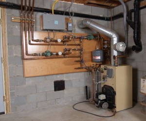
Original heating system, prior to piping modifications

Original heating system, prior to piping modifications

The boiler loop along with the zone takeoffs can be seen in the above picture in the original system. The new wood boiler will be located somewhat to the right of where the oil boiler is located to allow more access to the left side (the oil boiler will be removed). Because of the height of the wood boiler, the spirovent and expansion tank must be relocated to a higher position. The storage tank takeoff loop will be added at that time as well.

When the house was designed 12 years ago, the calculated total heat loss was 46770 Btu/h with 1 degree F. outsided temperature and 70 degrees inside. The system boiler load was calculated to be around 84809 Btu/h, excluding the supply and return piping. According to the logs kept by the system controller, it would seem the heat loss is somewhat lower than what was predicted, based on amount of oil used. But since we keep the upstairs at 64 degrees and downstairs at 68, that probably has something to do with it…

« Previous PageNext Page »