If you’ve owned or currently own a Saab 9000 you’ve no doubt experienced issues with the central locking system.¬† There seem to be two main failure characteristics: fuse blowing, or intermittent operation.¬† A central locking system that blows the fuse consistently generally has a bad motor someplace.¬† Since all 5 motors (doors plus the gas filler door) are wired in parallel there is no simple way to find the culprit.¬† Fortunately the doors all disconnect easily where the cables go into the A and B pillars.¬† It’s getting the connectors back on that’s a pain.¬† But a “divide and conquer” approach is the only way to find the culprit.¬† There are many sources of info on the web, and plenty of FUD as well.¬† Bad wiring is not normally an issue in the 9000.¬† Note that the radio receiver for the key fob is not part of the central locking “controller”.¬† All that the central locking controller does is provide a timed 0.7 second pulse of current one way or the other through all of the central locking motors to either lock or unlock all doors.¬† Input comes from the key fob radio receiver, a switch in the driver’s door activated by the key, and the lock/unlock switch on the center console.¬† If the lights flash in response to the key fob then all of that is probably working.¬† If the central locking responds properly to the console switch but not the driver’s door key then the problem is most likely in the door.¬† Note also that all of the doors must be closed for the central locking system to activate.
For intermittent operation the problem is most likely dodgy relays inside the central locking controller.¬† If the lights flash in response to the key fob, and in response to the center console locking switch it sounds like the locks try to open but won’t close, or vice versa, then most likely the problem is bad relays in the central locking controller.¬† There’s a lot of FUD on the web about ‘cracked solder joints’ and the like with regard to this but the controller PCB is conformally coated and located in a protected area above the steering column up in the driver’s footwell.¬† Most likely it’s just the relays, but it’s worth checking the connections that are exposed (not coated) to the large connector.¬† This is 1980’s technology, meaning you don’t have to worry about dealing with lead free solder, just use a good quality 63/37 tin-lead solder.

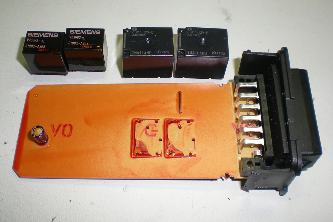
Saab 9000 Central Locking Controller
The Siemens relays used in the central locking controller are no longer available.¬† Plus, being sealed, there’s no good way to clean and burnish the contacts.¬† It’s a lot easier to simply sort two new 15A automotive relays from DigiKey or other source.¬† I used two Panasonic JSM1-12V-5 (DigiKey part number 255-1240-ND) because they had 15A contacts and the width of the relay is the same as the height of the original relays so these would fit in the original enclosure with no problems.¬† It takes a little bit of a kludge to wire in the new relays, but this is easy.¬† Plus, the relays were only $1.72 each from DigiKey.¬† Here’s how to do it.¬† First, open the controller and remove the board by releasing the two catches on each side of the connector.¬† A small screwdriver and a knife blade are your friends here.

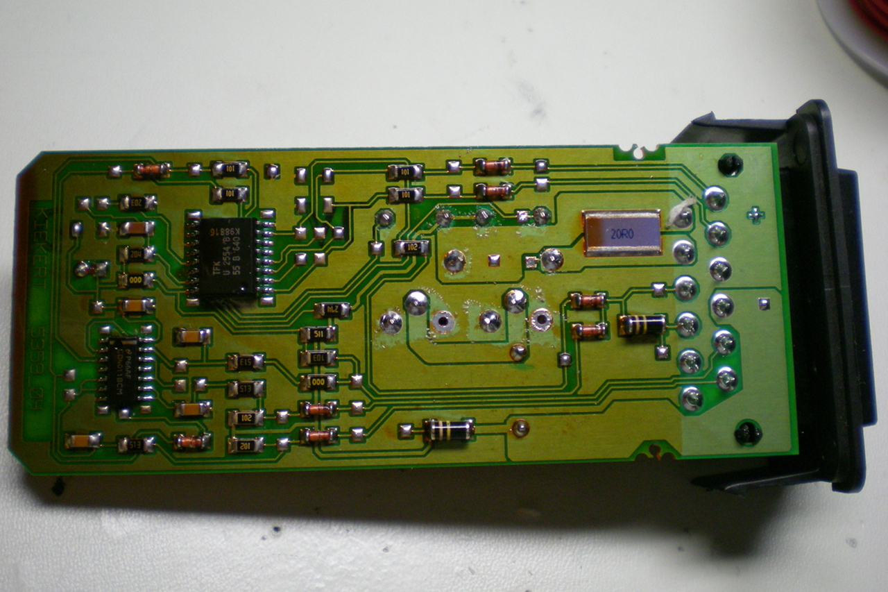
Desoldering relays from controller PCB
Once the board has been freed from the enclosure, proceed to desolder the relay pins from the board.  A solder puller or solder wick makes this easy.  The orange coating is conformal coating to prevent issues with moisture.  Heating the joints with the soldering iron is the best way to remove the coating at the joints and  a lot less messy than using solvents.
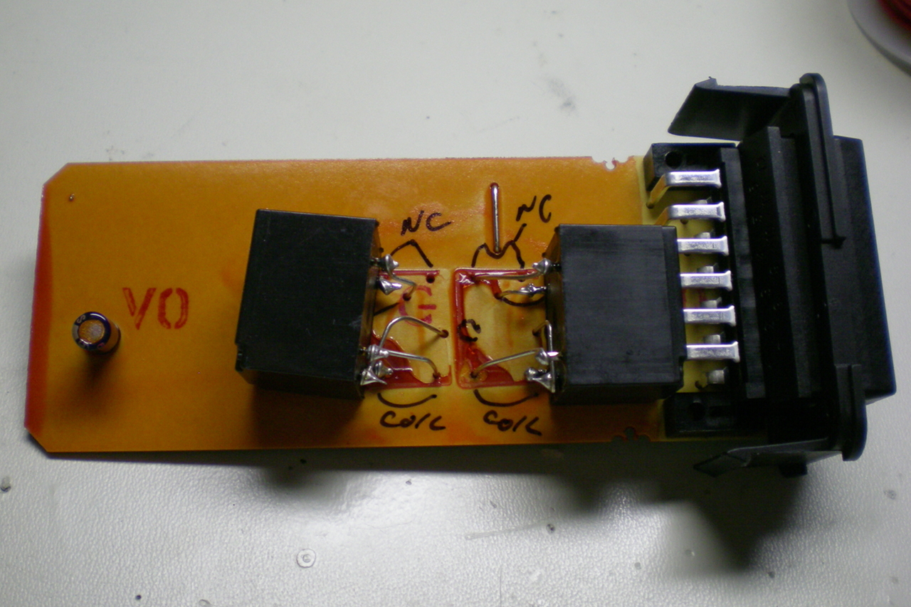
Controller top side with relays removed
Once the solder is completely removed from the relay leads it might take some gentle prying with a knife or small screwdriver to get the relays off the board.¬† As you can see in the image above the conformal coating wicks up under the relays and glues them to the board.¬† But this stuff isn’t very strong and the relays will come right off.¬† Take a needle or piece of wire and clean the coating out of the holes so later you’ll be able to insert the wires connecting the new relays to the board.¬† The relay connections are shown below:
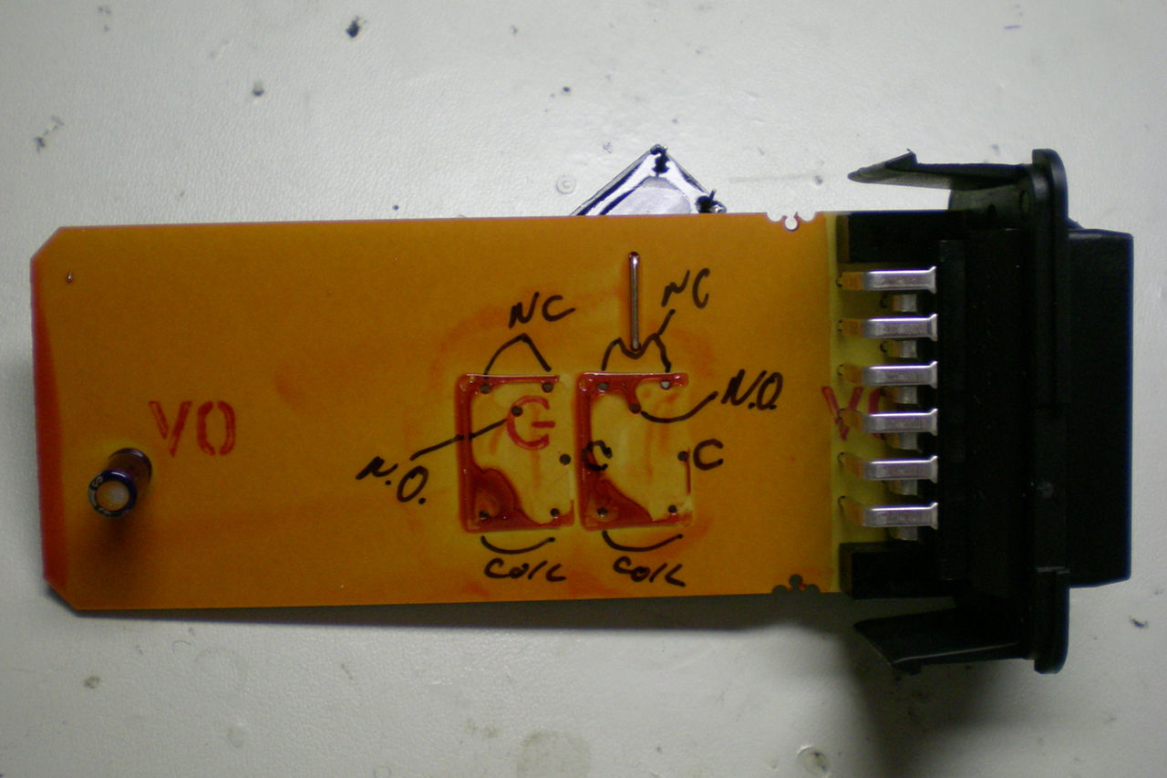
Relay connection positions
Looking at the bottom of the new relays, determine which pins are the coil connections, the common connection, and the NC (normally closed) and NO (normally open) pins.  Take some 22ga. solid wire and prepare the two new relays for attachment to the board:
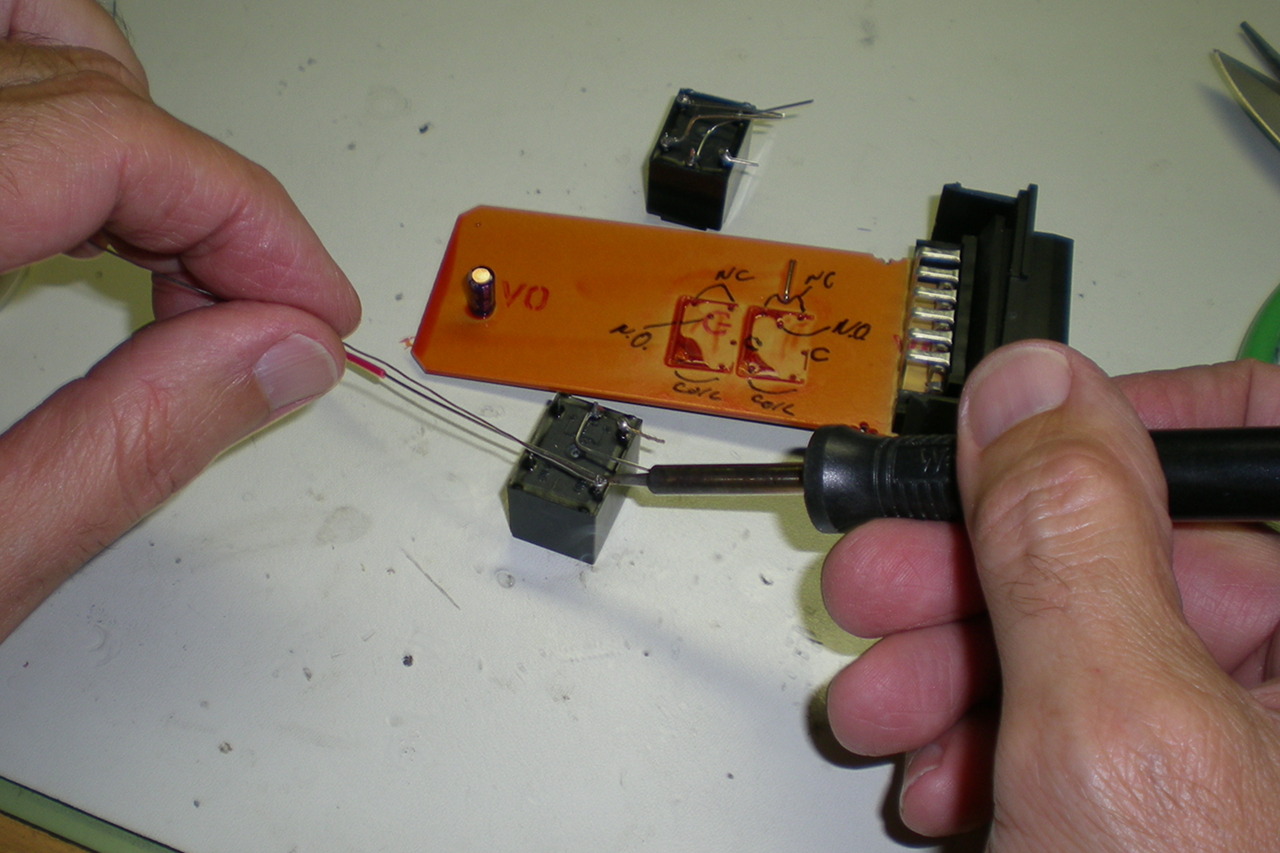
Attaching relay leads

Two relays with prepared leads
Now simply poke the leads of the relays through the board and solder them in place.¬† When making the first couple connections be sure to reheat the joints whilst squeezing the relay down onto the board.¬† There’s enough room for the new relays to fit into the inclosure provided they are pretty much down flush onto the surface of the board.
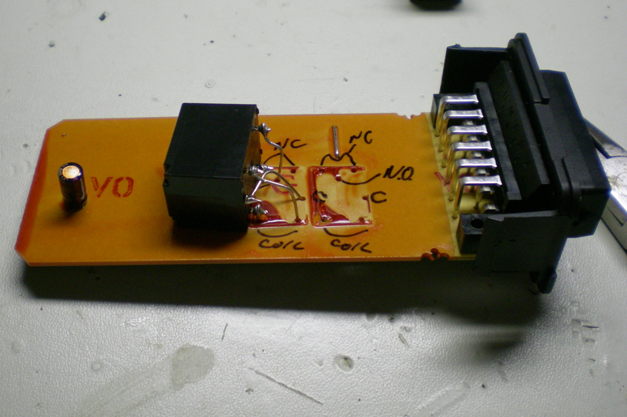
First relay positioned for soldering
Both relays fastened in place.
After soldering both relays in place, finish the job properly by cutting off the excess lead lengths on the back side of the board, and removing any flux residue with some alcohol or other suitable solvent.
Controller bottom side, after trimming and cleaning
Note we have two extra holes left over from the job.¬† The Siemens relays for some reason had two leads for the NC contact.¬† You can see from the pattern of the copper on the back side that these are tied together, so either hole position will work when fitting up the NC contacts from the new relays.¬† Be sure to get the contacts connected to the right place!¬† Don”t get NC/NO mixed up or your central locking function will reverse or worse yet you’ll create a constant path to ground through the motors and keep blowing fuses.¬† Another minor irritant is the the 15A central locking fuse that provides the 12V for the relays and door motors likes to pop if you cycle the locks too many times in succession too close together.¬† If the fuse blows after the first time you try to lock or unlock the doors you may still have a bad motor someplace.¬† Try a 20A fuse instead.¬† If the lock motors work normally after that, cycle them once or twice, then try a 15A fuse again.¬† If the motors have not been activated in a while they might be a bit stiff.
All of the manual door locks should operate freely.¬† If one or more of those are very stiff then it may be time to disassemble the door panel and try to lube things or replace the offending motor.¬† If someone has busted your rear manual door lock plunger that’s a simple fix.¬† There’s a bellcrank assembly that connects to the plunger, then a long rod along the door back to the lock mechanism.¬† Someone tried to save a nickel way back when and used a plastic pin for the bellcrank pivot that shears off at the least provocation.¬† A #8 screw, nut and washers is all it takes to fix this common problem.


